German experimental armor development, part I: target arrays for trial program 16, 21 and 22

This article is largely based on the declassified report “Bericht über die Erprobungspogramme 16, 21 und 22, durchgeführt in der Zeit vom 9.05 bis 13.05.1977 und vom 14.11 bis 18.11.1977 bei der Erprobungsstelle 91 der Bundeswehr in Meppen; B – TU 1911/00” by the company Industrieanlagen-Betriebsgesellschaft mbH (IABG), though it might include a few author’s additions, while some parts of the report might have been omitted due to not being relevant or interesting. Sections written as quotes are direct translations, though these were made by someone who is not a trained/professional translator.
Summary
In the trial program 16 an active hull add-on armor systems with shock-dampened mountings was fired at. External ignition was used to ensure the initiation of the explosive foil. Using this external ignition an increased protection capacity of the active armor compared to a similar, inert armor array was proven.
B – TU 1911/00, page 2
In the trial program 21 the influence of a front plate in the protection capacity of active armor was investigated. A front plate aids the effect of the active armor against the impacting projectile. A front plate of higher strength seems to amplify this effect.
B – TU 1911/00, page 2
The trial program 22 serves to dermine the protection capacity of an active armor array against shaped charge fire (96 mm). Furthermore it could be showcased that crystalline non-phlegmatised nitropenta reacts with a detonating transformation upon projectile impact.
B – TU 1911/00, page 2
Please note that the term “active armor” at the time was used in Germany in reference to explosive reactive armor (ERA). For the sake of readability, the abbreviation “ERA” or the terms “reactive armor” and “explosive reactive armor” might be used in the following texts.
1. Test procedure
In the time from 9.05 to 13.05.1977 and in the time from 14.11 to 18.11.1977 the trial programs 16, 21 and 22 were conducted at the testing site 91 of the Bundeswehr in Meppen in the firing position 15.000.
The trial programs 16 and 21 included the firings against respectively one frontal hull add-on armor array based on the principle of active armor that had been fitted using shock-absorbing mounts while measuring the shock at the tank hull.
The trial program 22 intended the shelling of two single target arrays based on the principle of active armor. One static firing and a live-firing were conducted
B – TU 1911/00, page 6
1.1 Weapon
All shots were fired from a tank gun (105 mm, smooth bore) with a Leopard 1. The following ammunition was used:
105 x 617 mm APFSDS (KE/38)
Lot: RH-E-150 at +21°C
The distance to the target was 100 metres.
B – TU 1911/00, page 6
So this specific German ERA was designed to “protect” a Leopard 1 hull against hits from 105 mm APFSDS rounds; more specifically against hits with the experimental KE/38 APFSDS made by Rheinmetall, fired from a smoothbore gun from the same company. The KE/38 APFSDS round was also used for firing trials against a captured T-62 tank (given to West-Germany by the Isreali government) and was used as one of multiple reference threats in the Leopard 2 protection requirements.
The projectile velocity (v30m respectively v50m) was measured for each shot at a distance of 30 metres (in the trial program 21 and 22, the distance was 50 metres) from the gun.
The v30m values ranged between 1,362.9 metres per second and 1,375.0 metres per second, and the v50m values ranged between 1,362.3 metres per second and 1,383.3 metres per second.
B – TU 1911/00, page 6
The shaped charge used in trial program 22 was a 96 mm shaped charge warhead of the type Milan.
B – TU 1911/00, page 7
1.2 Targets
1.21 Target set-up of trial program 16
The target set-up, whose shelling is content of the trial program 16, was a widespread active armor with the dimensions of 1,000 by 2,000 millimeters (image 1). This set-up was adapted onto the upper front armor plate of a Leopard 1 hull with shock-absorbing mountings. The individual steel plates of the add-on armor were mounted parallel to the upper front plate of the Leopard 1 tank, i.e. the angle of firing was 60° NATO.
Seen from the direction of the shots, the following arrangement was used for shots 1 to 4:
B – TU 1911/00, page 7
- a front plate consisting of 20 mm armor-grade steel
- 20 mm stand-off distance
- an active sandwich consisting of:
- a frontal 10 mm thick flyer plate
- a 4 mm thick explosive foil
- a rear 10 mm thick flyer plate
- 176 mm stand-off distance
- witness plate I made of 40 mm armor-grade steel (note: this is described as rear armor I in image 1)
- witness plate II made of 40 mm armor-grade steel (note: this is described as rear armor II in image 1)
- 160 mm stand-off distance
- the hull armor plate
For the inert shot 5 the following array was used instead:
B – TU 1911/00, page 9
- a front plate consisting of 20 mm armor-grade steel
- 20 mm stand-off distance
- 10 mm steel
- 10 mm steel
- 120 mm stand-off distance
- witness plate I made of 60 mm armor-grade steel
- witness plate II made of 40 mm armor-grade steel
- witness plate III made of 40 mm armor-grade steel
1.22 Target set-up of trial program 21
The target set-up, whose shelling is content of the trial program 21, was a widespread active armor with the dimensions of 1,000 by 2,000 millimeters (image 2). This set-up was adapted onto the upper front armor plate of a Leopard 1 hull with shock-absorbing mountings.
The individual steel plates of the add-on armor were mounted parallel to the upper front plate of the Leopard 1 tank, i.e. the angle of firing was 60° NATO.
Seen from the direction of the shots, the following the shots 1 to 7 were presented with the following active armor arrangement:
B – TU 1911/00, page 9
- front plate made of 20 mm armor-grade steel
- 100 mm stand-off distance
- an active sandwich consisting of:
- a 3 mm thick frontal flyer plate
- a 5 mm thick explosive foil
- a 10 mm thick rear flyer plate
- 160 mm stand-off distance
- a witness plate made of 115 mm thick armor-grade steel
- 60 to 190 mm stand-off distance
- the hull armor plate
1.2.3 Target set-up of trial program 22
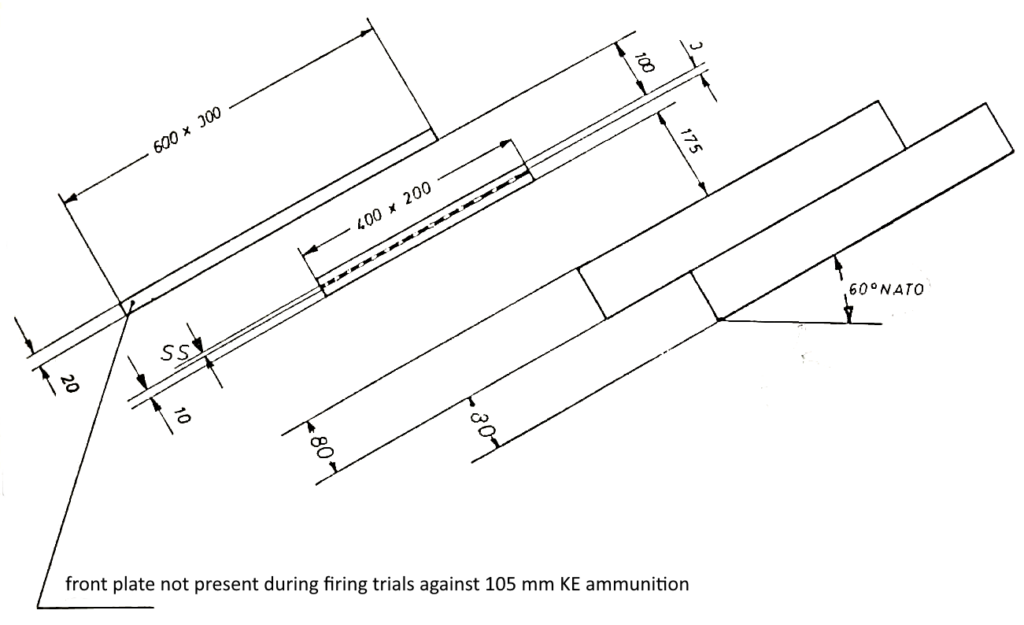
The target set-up for the trial program 22 (image 3) is an armor based after the active [armor] principle, where the plates are arranged under 60° NATO angle. In the direction of firing the following arrangement was present:
B – TU 1911/00, page 11
- 20 mm armor-grade steel (front plate)
- 100 mm stand-off distance
- active sandwhich conisting of:
- a 3 mm thick frontal flyer plate
- a 5 mm thick explosive foil
- a 10 mm thick rear flyer plate
- 175 mm stand-off distance
- 80 mm armor-grade steel (witness plate I)
- 80 mm armor-grade steel (witness plate II)
During the firing with 105 mm KE ammunition no front plate was used.
B – TU 1911/00, page 11
1.3 Used materials
The test set-up for the trial program 16 used an armor-grade steel plate of quality grade C as front plate. The intermediate armor (witness plate I, II) and the rear armor (witness plate III) were made as armor-grade steel plates of the quality grade B. The overlaid plates [a more modern translation would be “flyer plates”] for the active sandwiches were plate made by the company Schoeller und Bleckmann with the product name Himalaja.
B – TU 1911/00, page 11
The test set-ups for the trial programs 21 and 22 used armor-grade steel plates of quality grade V as front plates. The overlaid plates for the active sandwiches were plate made by the company Schoeller und Bleckmann with the product name Himalaja. The rear armor (witness plates) consisted of armor-grade steel of the quality grade A.
B – TU 1911/00, page 13
| Hardness scale HB 30 | |
| HZB 20 – A | 260 – 300 |
| HZB 20 – B | 308 – 353 |
| HZB 20 – C | 338 – 383 |
| HZB 301 – V | 450 – 490 |
| Hardness HRC | |
| Himalaja | 27.6 |
| Material | Standard designation | C | Si | Mn | P | S | Cr |
| Himalaja | X 120 Mn 12 | 1.205 | 0.36 | 12.155 | 0.036 | 0.0135 | 0.27 |
1.4 Explosive materials
For the explosive material layer of the active sandwiches was a flexible foil made of 85% PETN (Nitropenta = Pentaerythritol tetranitrate) and 15% natural rubber (patented by Kegler) from the company Schweiz. Sprengstoff-Fabrik A.G. Dottikon. In the trial programs 21 and 22 one time respectively crystalline nitropenta (ca. 600 g, condensed via rattling) was used.
B – TU 1911/00, page 15
1.5 External ignition
During the penetration of a trigger foil mounted at the front face of the test arrangement by the projectile, a short circuit is caused, which provides the start impulse for the tirgger device. The time delay after which the trigger device outputs an electric impulse is selected in such a way, that it corresponds to the flight of time of the projectile from trigger foil to active sandwich. An instantaneous fuse PL 464 of the company Dynamit Nobel is set off by the electric impulse, which initiates detonation of the explosive foil. As transfer charge between instantaneous fuse and explosive foil the “Sprengmasse, formbar” as introduced with the Bundeswehr is used.
B – TU 1911/00, page 15
In the next part of this series of articles, the results of the firing trials will be included and discussed.